Insert symbols and details into your drawings from commercial online sources or from your own designs.
In AutoCAD, a block is a collection of objects that are combined into a single named object. The following are some sample blocks at various scales.
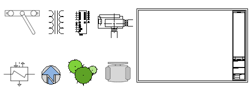
Some of these blocks are realistic representations of objects, some are symbols, and one of them is an architectural title block for a D-size drawing.
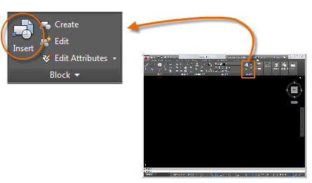
The first time you insert the drawing as a block, you need to click Browse to locate the drawing file. Make sure you organize your blocks into easy-to-find folders.
Once inserted, the block definition is stored in your current drawing. From then on, you can choose it from the Name drop-down list without needing to click the Browse button.
Tip: The default settings in the Insert dialog box are usually acceptable. After you choose the block name, click OK, and then specify its location in your drawing. You can rotate it later, if necessary.
Notice that when you insert a block, it is attached to your cursor at the point indicated. This location is called the insertion point. By default, the insertion point is the origin point (0,0) of the original drawing.
After inserting the block, you can select it and a grip appears. You can easily move and rotate this block using this grip.
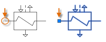
In the following example, a drawing file is inserted into the current drawing to provide a standard detail view.
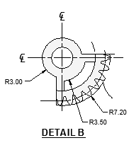
Note: Inserting a drawing file as a block provides a static reference to the specified drawing. For a reference that automatically updates, you can attach the drawing with the External References palette (XREF command) instead.
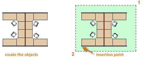
For example, this is how you could create a module for a cubicle design.
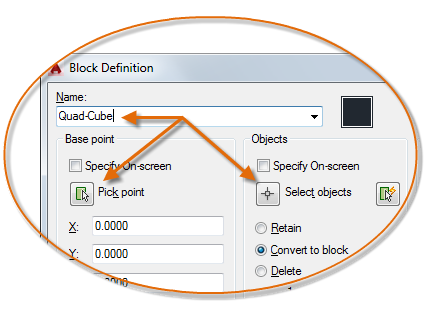
You can enter the information for steps 3, 4, and 5 into the Block Definition dialog box in any order.
After creating the block definition, you can insert, copy, and rotate the block as needed.

Using the EXPLODE command, you can explode a block back to its component objects if you need to make changes. In the illustration below, the cubicle on the right was exploded and modified.

In this example, you would probably create a new block definition from the objects in the exploded block.
Note: You can create block definitions that include one or more attributes that store and display information. The command that you would use is ATTDEF. Typically, attributes include data such as part number, name, cost, and date. You can export block attribute information to a table or to an external file.
In AutoCAD, a block is a collection of objects that are combined into a single named object. The following are some sample blocks at various scales.

Some of these blocks are realistic representations of objects, some are symbols, and one of them is an architectural title block for a D-size drawing.
Insert a Block ==>
Typically, each of these blocks is an individual drawing file, perhaps saved in a folder with similar drawing files. When you need to insert one into your current drawing file, you use the INSERT command (or enter I in the Command window).
The first time you insert the drawing as a block, you need to click Browse to locate the drawing file. Make sure you organize your blocks into easy-to-find folders.
Once inserted, the block definition is stored in your current drawing. From then on, you can choose it from the Name drop-down list without needing to click the Browse button.
Tip: The default settings in the Insert dialog box are usually acceptable. After you choose the block name, click OK, and then specify its location in your drawing. You can rotate it later, if necessary.
Notice that when you insert a block, it is attached to your cursor at the point indicated. This location is called the insertion point. By default, the insertion point is the origin point (0,0) of the original drawing.
After inserting the block, you can select it and a grip appears. You can easily move and rotate this block using this grip.

In the following example, a drawing file is inserted into the current drawing to provide a standard detail view.

Note: Inserting a drawing file as a block provides a static reference to the specified drawing. For a reference that automatically updates, you can attach the drawing with the External References palette (XREF command) instead.
Create a Block Definition
Instead of creating a drawing file to be inserted as a block, you might want to create a block definition directly in your current drawing. Use this method if you do not plan to insert the block into any other drawing. In that case, use the BLOCK command to create the block definition.
For example, this is how you could create a module for a cubicle design.
- Create the objects for the block.
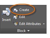
- Start the BLOCK command.
- Enter a name for the block, in this case Quad-Cube.
- Select the objects that you created for the block (click 1 and 2).
- Specify the block insertion point.

You can enter the information for steps 3, 4, and 5 into the Block Definition dialog box in any order.

After creating the block definition, you can insert, copy, and rotate the block as needed.

Using the EXPLODE command, you can explode a block back to its component objects if you need to make changes. In the illustration below, the cubicle on the right was exploded and modified.

In this example, you would probably create a new block definition from the objects in the exploded block.
Note: You can create block definitions that include one or more attributes that store and display information. The command that you would use is ATTDEF. Typically, attributes include data such as part number, name, cost, and date. You can export block attribute information to a table or to an external file.


No comments:
Post a Comment